A high-rise fire sprinkler pipe specification should be developed by pressure zone, not applied uniformly from the pump room to the top floor. The water supply must overcome elevation to serve the upper floors, but that same supply can expose lower floors to much higher static pressure. Pumps, tanks, pressure-control devices, testing requirements, and friction losses add further differences between zones.
The practical sequence is to divide the building into hydraulic zones, establish each zone’s controlling pressure, and select all pressure-retaining components as one assembly. A traceable submittal then helps reviewers identify an underspecified component before purchasing or installation.
Why High-Rise Buildings Need Pressure-Zoned Fire Sprinkler Piping
Height changes pressure even when the pipe diameter and material remain the same. To deliver the required flow to sprinklers on an upper floor, the water supply must overcome both elevation and friction. Elevation therefore becomes a major input in the project hydraulic calculation.
The lower part of the same riser does not experience the same condition as the top. During a fire flow, friction through pipe, fittings, and valves consumes part of the available pressure. When flow stops, that friction loss disappears. The lower floors may then see the full effect of the water-supply pressure plus the vertical water column. A fire pump may also produce its highest outlet pressure at little or no flow, rather than at its rated duty point.
If the building were one unrestricted zone, the supply needed upstairs could exceed the permitted pressure of lower-floor components even when the steel pipe itself appeared adequate.
Designers control this difference by using arrangements such as separate risers, pressure-reducing valves, intermediate tanks, or dedicated zone pumps. Each arrangement creates a hydraulic boundary. Once that boundary exists, the question is no longer whether one pipe is suitable for the entire building. The question becomes whether every component inside each zone is suitable for that zone’s maximum operating condition and required test condition.
Pressure zoning therefore determines both hydraulic performance and material selection. It prevents the upper-zone demand from becoming an unchecked lower-zone pressure and gives the project team a rational basis for specifying different components where the pressure conditions genuinely differ.
Establish the Design Basis and Divide the Building into Pressure Zones
The zoning decision begins with the project design basis. National regulations, the local fire authority, insurer or owner requirements, and the contract may impose different approval routes. A European project may reference a national adoption of EN 12845, an Australian project may use the relevant AS 2118 requirements, and a Middle Eastern project may add civil-defence or conformity requirements. The route must be confirmed from the project location and documents.
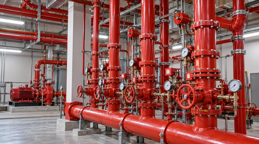
The supply arrangement is then read together with those requirements. The riser diagram should show the elevation of the water source, fire pumps, tanks, pressure-reducing stations, check valves, and branches serving different floor groups. These are not merely items to list: each one changes how pressure reaches the pipework.
A tank adds pressure according to elevation, while a pump adds pressure according to its performance curve and inlet condition. A pressure-reducing valve creates a new downstream condition only when its inlet range, outlet setting, flow range, and no-flow performance are suitable.
The engineer can now draw each zone boundary at the location where the hydraulic condition changes. For every zone, the design record should identify the served floors, the supply path, the highest and lowest pipe elevations, the pressure-control device, and the hydraulically demanding point. The top of a zone often controls the available residual pressure, while the bottom often experiences its highest static pressure. Checking only one end misses half of the decision.
This stage should produce a pressure-zone schedule, not a general note saying that all piping must suit system pressure. The schedule becomes the shared reference for the hydraulic calculation, drawings, equipment selection, pipe specification, and later submittal review.
Determine the Controlling Pressure in Each Fire Sprinkler Zone
Once the boundaries are known, each zone should be tested against three different conditions. They answer different questions and should not be collapsed into one unexplained pressure value.
The first is the design-flow condition. Water is moving toward the hydraulically demanding area, so the calculation includes elevation and friction losses. This establishes whether the supply can deliver the required flow and residual pressure at the remote sprinklers, but it does not establish the highest lower-zone pressure.
The second is the maximum non-flow or low-flow condition. With little or no demand, friction losses fall, while a pump may operate near its maximum outlet pressure. At the bottom of a zone, this condition can exceed the pressure calculated at the pump’s rated duty. Tank elevation, maximum inlet supply pressure, pump performance, and the behaviour of pressure-reducing devices must all be included. This is frequently the condition that controls the allowable working pressure of pipework components.
The third is the commissioning or hydrostatic-test condition required by the governing project documents. Test pressure is intentionally applied for a defined purpose and duration; it is not automatically the permitted continuous working pressure. The specification must confirm both that the assembly is suitable for normal maximum pressure and that it can undergo the required test procedure.
Transient pressure should be added where the system arrangement or project requirements identify a credible surge risk. It is not appropriate to invent a universal allowance. The designer should assess pump operation, valve closure, pressure-control response, and connected supplies, then apply the method required by the project.
The controlling result is therefore not simply the largest number copied from a data sheet. It is a documented design condition linked to an acceptance criterion: adequate residual pressure during flow, acceptable component pressure during maximum supply, and compliance during testing. Keeping those results separate prevents a test value from being mistaken for a continuous rating or a rated pump value from concealing a higher no-flow condition.
Turn Zone Pressure into Pipe and Connection Specifications
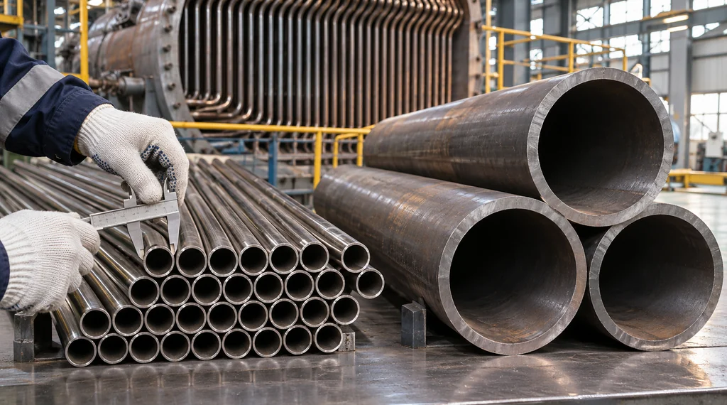
With the controlling conditions established, the project team can convert hydraulic results into a buildable pipe specification. Begin with the governing product standard, nominal size, outside diameter, wall thickness, material grade, coating, and end preparation. The wall designation should never stand alone; DN or NPS, actual outside diameter, and wall thickness should be stated wherever different dimensional systems could create ambiguity.
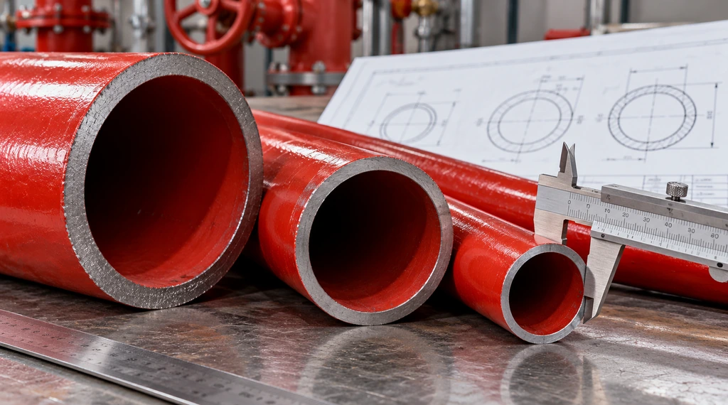
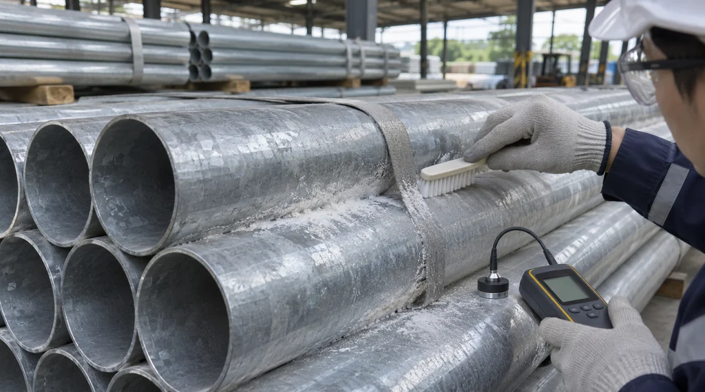
The fire sprinkler pipe range shows welded and seamless options with different coatings and end preparations. Where a European pressure-tube route is written into the contract, the available dimensions and processing of EN 10216-1 seamless fire-fighting pipe can be checked against the approved specification. A product page helps screen options but does not prove project acceptance.
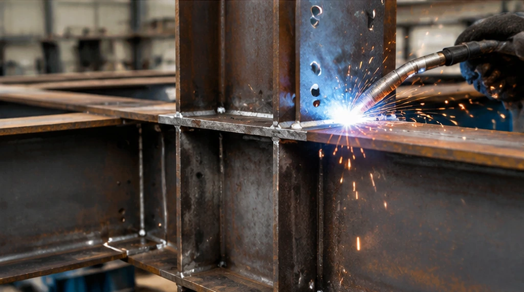
The connection method comes next because it can change the acceptable wall and end preparation. A grooved joint requires compatible pipe dimensions, groove geometry, coupling, gasket, and pressure classification. Threading removes material, so the remaining wall must be suitable for the thread and service condition. Welding requires an approved procedure, qualified execution, inspection, and repair of any coating affected by fabrication. Flanged interfaces require compatible flange dimensions, pressure class, gasket, bolts, and connected equipment.
The choice should follow installation and maintenance needs rather than habit. Grooved joints can support rapid assembly and access, threading may suit smaller sizes with adequate wall, welding may suit controlled permanent fabrication, and flanges serve equipment interfaces. None is universally superior.
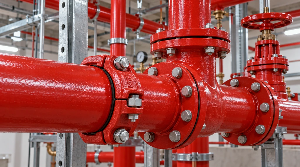
Finally, verify the complete pressure boundary. The pipe, coupling, fitting, valve, gasket, flexible connector, and pressure-control device do not combine into an average rating. The most restrictive applicable component or configuration limits the assembly. Ratings may also change with diameter, temperature, gasket material, groove type, or certification scope. This is why selecting a thicker pipe alone cannot correct an incompatible coupling or valve.
For a closer examination of the terminology used at this stage, the guide to working pressure and test pressure explains why product ratings, system pressure, and test conditions must be checked separately.
Prepare a Reviewable High-Rise Fire Sprinkler Pipe Submittal
The submittal should allow a reviewer to trace each pipe and connection decision back to a hydraulic condition. A collection of product catalogues is not sufficient because it does not show which pressure zone each product serves or which design condition controls its selection.
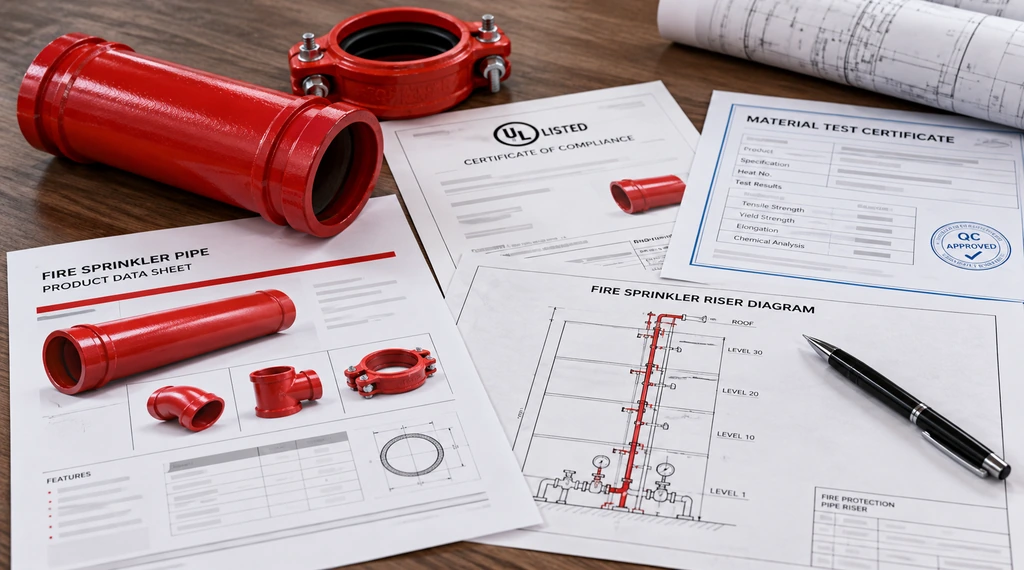
For every pressure zone, the submittal should establish the following verification chain:
| Review stage | Information to record | What the reviewer should be able to confirm |
|---|---|---|
| Zone definition | Served floors, upper and lower elevations, supply path, and pressure-control boundary | The drawings and hydraulic calculations refer to the same physical zone |
| Pressure basis | Required flowing pressure, maximum non-flow pressure, test condition, and any project-required transient assessment | The controlling pressure has been derived from the applicable operating condition rather than copied from a product data sheet |
| Pipe and joint selection | Product standard, grade, outside diameter, wall thickness, coating, end preparation, and connection method | The selected pipe dimensions and joint preparation are compatible |
| Component pressure check | Ratings of couplings, fittings, valves, gaskets, flexible connectors, and pressure-control devices | No component has a lower applicable rating than the zone requires |
| Compliance evidence | Product data sheets, certificates, material records, coating documents, and installation instructions | The submitted evidence covers the proposed manufacturer, product, size, wall, and connection configuration |
This verification chain should be completed separately for each actual zone identified on the approved riser diagram. The project team does not need to assume that the lower, middle, and upper zones use different pipe specifications. It does need to prove that the specification selected for each zone is suitable for that zone’s pressure conditions.
For example, the lower zone may be controlled by the maximum non-flow pressure at its lowest elevation. An upper zone may be more demanding during system operation because the supply must overcome elevation and friction before maintaining the required residual pressure at the remote sprinklers. A zone downstream of a pressure-reducing valve requires both the upstream pressure range and the valve’s downstream performance to be documented. These conditions can lead to different component requirements even when two zones ultimately use the same steel pipe.
Support the completed zone records with the approved riser diagram, hydraulic calculations, pump curve, water-supply information, pressure-control-device data, component data sheets, and contract-required inspection or certification documents. Each certificate should be checked for its actual manufacturer, product family, dimensional range, connection configuration, and validity. Its title alone does not prove that the proposed product is covered.
This structure also makes conflicts visible before procurement. If the calculations and drawings show different zone boundaries, the controlling pressure cannot be traced. If a substitution changes the wall thickness or groove geometry, the pipe-and-coupling combination must be reassessed. If a valve or coupling has a lower applicable rating than the pipe, that component limits the assembly.
The final submittal should therefore produce one traceable result for every pressure zone: the controlling design condition, selected pipe and joint system, limiting component, and supporting evidence.
Reduce High-Rise Fire Pipe Submittal Rework
For a useful technical review, buyers can share the project location, applicable standard, pressure-zone schedule, calculated operating and test conditions, pipe dimensions, connection method, coating requirement, and required compliance documents. These inputs help reveal dimensional conflicts, unsupported component combinations, and missing records before the order is fixed.
Baolai supplies steel fire-protection piping and related processing for international projects. Project teams can confirm high-rise fire sprinkler pipe requirements against the requested dimensions, connection preparation, coating, and documentation so that unsuitable options are removed earlier and the final submittal is easier to review.
FAQs
Does a higher-pressure zone always require seamless steel pipe?
No. Higher pressure alone does not automatically make seamless pipe necessary or welded pipe unsuitable.
The acceptable manufacturing route depends on the product standard, material grade, dimensions, wall thickness, joint system, required pressure performance, and project approval conditions. A compliant welded pipe may be suitable for one high-pressure application, while a project specification may require seamless pipe for another. Buyers should compare the exact product configuration and supporting documents rather than treating the manufacturing route as a pressure rating.
Can sprinkler and standpipe systems use the same pressure-zone assumptions?
Not automatically. Sprinkler and standpipe systems can share parts of a water supply or riser arrangement, but their required flows, residual pressures, operating scenarios, and local approval requirements may differ.
A pressure zone established for sprinkler demand should not be copied to a standpipe system without a coordinated hydraulic review. Where systems share pumps, tanks, risers, or pressure-control devices, the design team should identify which operating scenario controls each common component.
Should pipe downstream of a pressure-reducing valve be selected only for the valve’s normal outlet setting?
No. The normal outlet setting is only one condition that may affect downstream pipework.
The design must also consider the valve’s performance at different flows, maximum inlet pressure, no-flow outlet behaviour, bypass arrangements, parallel valves, and the consequences of malfunction where required by the governing project criteria. The permitted downstream component pressure should be established by the qualified system designer, not inferred from the valve nameplate setting alone.
Sources
- BS EN 12845, fixed firefighting systems and automatic sprinkler-system design, installation, and maintenance; confirm the current national adoption required by the project.
- ISO/TC 21/SC 5, international standardisation scope for fixed firefighting systems using water and related components.
- FM Data Sheet 3-11, pressure-regulating-device guidance where this insurer or contract route is specified.